

| News | |
| 28OCT13 | Assembly and debug instructable available at http://www.instructables.com/id/How-to-Build-a-5-Channel-Flame-less-LED-Candle-Sim/ Kits available at https://www.tindie.com/products/tymkrs/led-candle-simulator/ And added a new video of the candle installed in a jack-o-lantern pumpkin. |
| 02OCT13 | Fixed font on raw card and added value edition. |
| 01OCT13 | Woot make hack-a-day http://hackaday.com/2013/10/01/leds-turn-the-heat-up-on-flameless-pumpkin-lights/ |
| 29SEP13 | New design work is done and prototype is up and running. |
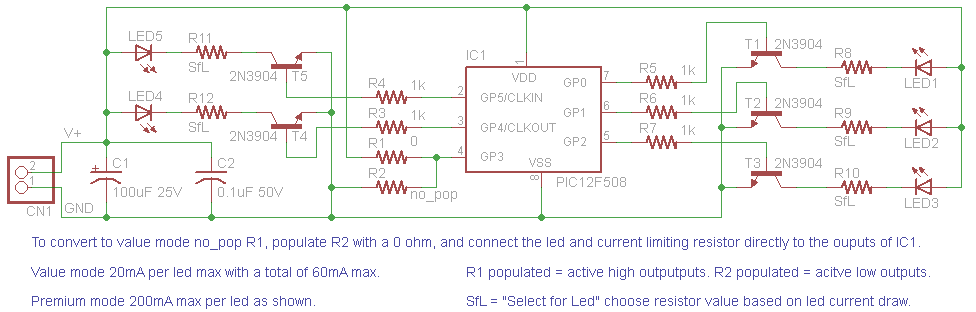
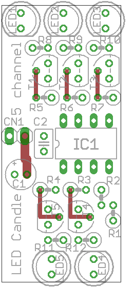
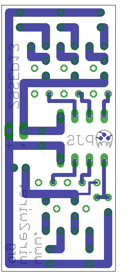
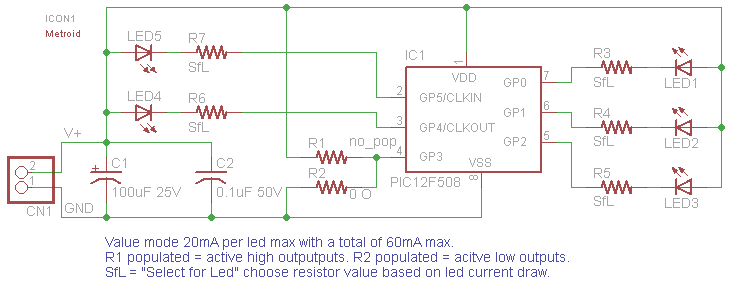
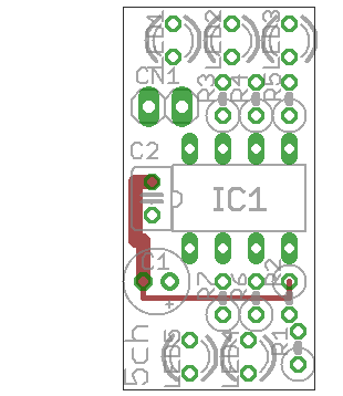
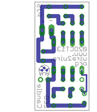
| Download the full package (micro code and
PCB data) here [LED_candle.zip].
The core of this project is a PIC12F508 which was strictly picked based on cost and availability. This firmware should be easy to port to just about any PIC micro. Code only uses 1 timer, no interrupts, 22 bytes ram, and 369 words of flash. The core of the firmware is 5 independent 16 bit linear feedback shift registers generating pseudo random bit streams. These bits streams are used to generate both the brightness level and dwell of a given output to approximate the flicker of the candle. Also included in the firmware is a "wind" function that will randomly activate for a random amount of time that switches from the normal bright slow flicker to a dimmer fast flicker just as if there was a wind gust / draft in a room with a candle. In the firmware source code there is a set of constants near the top that can be used to customize the operation to taste. These include min / max brightness and dwell for both the normal and wind states as well as the wind gust timings. As stated in the logics and videos there are 2 different populations of this circuit value and premium. Value mode has the minimum parts count and is good for small candles and / or proto boarding. Premium has more parts and allows the brightest and smoothest flickering. (see videos) If using the value build make sure to limit your LED current to 20mA or less per LED and no more than 60mA for all LEDs attached to the micro. For the premium version the only limitation is 200mA per led with no practical group limitations. Even this limitation can be extended with the use of higher power NPN transistors and or LED drivers. Note if building the value version make sure to pull pin 4 of the PIC low instead of high. This sets the outputs to active low instead of high to drive the LEDs directly (else your flicker will be inverted). Power supply can either be a 5V adapter or a 6V battery pack. 6V is a little over recommended ratings but well under max. Also soon as the batteries start to run down a little it will be well under the 5.5V recommended max. On the topic of batteries the estimated life on a set of 4AA with 5 50mA LEDs is about 5 hours. Will update once I have some testings done. By picking lower power / less LEDs this time can easily be extended. To calculate the LED resistor value use this formula Rled = (Vsupply - Vled)/Iled if this does not result in a exact resistor value (more than likely) round the value up to the next larger resistor. Also water clear LEDs with a narrow (~25deg) seem to work best. |