

| News | |
| 5MAY13 | Made it just in time. Basic function is all there and working but some of the extended goals (touch screen and sound for example) are not finished yet. Will be adding them over the next few months as I add and debug more games. Entry video time laps video |
| 26APR13 | Red Bull Creation contest theme this year is "interactive lights" convinced the team to take on my side project for the compition. So a multi year get it done whenever project now needs to be complete in a little over 2 weeks with additional features and a video made. |
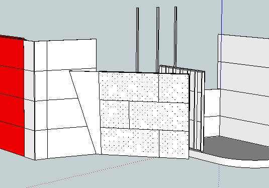
| 1MAR13 | E-Week is done (built 40 marble lifts) and back to work on the wall. Cutting wire and attaching LEDs. |
| 25SEP12 | Raw cards are built up and prototype firmware seems to work. ILEO and E-Week planning is starting up so may be a while before I do anymore. |
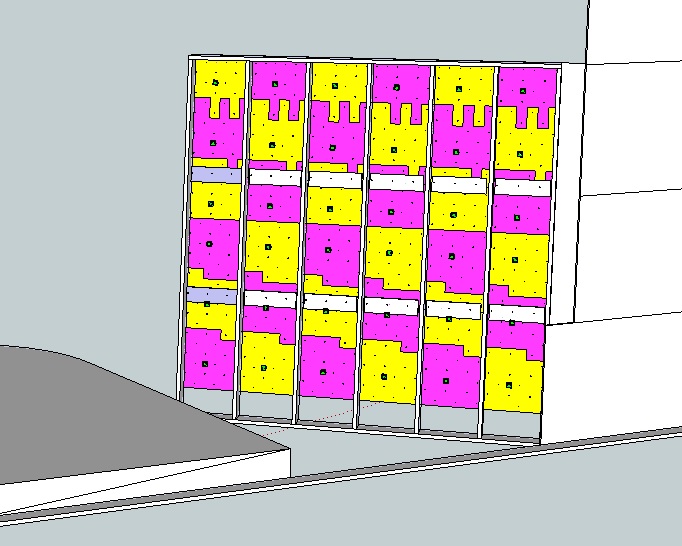
| 24JUL2012 | In process of building up the raw cards (27 / 40 done)
and started putting this web page together |
| OCT2010 |
First planning phase started (oldest revision date I
can find on my spreadsheets) |
| Technical details: 32 TnB cardlets with 256 touch sensitive inputs and 288 RGB led outputs total. RS-485 interconnect network running at 57.6kbps. BOM, costs, and raw packet format can be found on my spreadsheet. Cad drawings, Logic diagrams, Firmware, and Gerber data can be found in this zip file TnB0z.zip. (to be posted once the wall is installed and debugged. If you want it sooner drop me a email.) Other than the TnB hardware there is a RS-485 -> RS-232 converter for the connection back to the PC. (point to point wiring will include the logics for it in the TnB0z.zip file (see above). A PC power supply to feed 5V to all the hardware and 12V to anything else we may need (fan??, PC speakers, extra lights, ect). And lastly some sort of PC to run the show. This will more than likely be the last item addressed. For the inital install and debug I can just use my laptop. Once the Wall is built and debugged we can chase down a donor pc. (Past experience has proven climbing gyms are very hard on PCs) Programing: To see the current list of games supported see the software page here. (to be added once the software is running) There are 3 levels you can program the wall at Low, Mid, and High level. -The low level is at the TnB interface level via serial commands. See my spreadsheet for details on the format and content of the data packets. This level is for programmers experienced with RS-485 networks and the PC hardware needed to drive them (There is a RS-232 to RS-485 converter hanging off the PC.) - The mid level interface is programed in perl. This takes care of all the wall communication and management and exposes a set of API functions to set the LED and detect when I hold is touched. Once the initial software is up and running I will create a link to the code and documentation here. - The high level code will be a gui based point and click environment for building up game flows. Current idea is you would pick the holds on the screen for the next event trigger. Then pick the leds and colors you want to happen on that event. This code will more than likely be added later as I need to find help on the GUI half of the code. Other interesting details. - The lens caps for the LEDs are 10-32 x 1/2" Polycarbonate screws from McMaster-Carr. The Plywood was just drilled and tapped to accept the screw on the front and drilled to a press fit on the back for the 5mm LED body. A small dab of glue makes sure the LEDs don't pop out. Reason for using the screws is it allows them to be removed it a hold overlaps them and also allows them to be replaced if broken or scuffed up. - The touch sensors are wired into the T nut for each hold. That way the T nut and the bolt holding the hold on become part of the sensor. On large holds the surface area of the sensor can be increased by applying a layer of metal foil tape (typically used in Hvac) to the back of the hold and having it come in contact with the mounting bolt. Also special holds could be made with a metal mesh cast into them. As long as the metal connects back to the bolt (ie connected to the mounting washer) it will expand the touch sensitive area of the hold. - Each led is independently controlled in 4 time slices. For each time slice you can set any combination of the 3 colors on. This results in 7 possible colors + off per slice. The slices allow both solid on / off and hardware blinking at 4 different rates. Also if you set the slices to different colors you can have the led blink back and fourth between those colors all in hardware. |
| The bulk of the
electronics of
the wall is based on the Touch aNd Blink (TnB) hardware. The TnB is
based off a PIC16F722A micro controller. The industrial version was
intentionally picked for it's higher total sink/source current capacity
over the extended part (200mA vs only 120mA). With all 9 LEDs on
Drawing near 20mA each the extended parts 120mA would be exceeded. The input power is expected to be regulated 5V. The PIC16F722A has a internal low drop out regulator. As such, even if the input power does droop the only noticeable affect should be the leds are slightly dimmer. In theory the 16F part should be able to run all they way down to 1.8V although at that point the green and blue LEDs would no longer function. The card includes 4 decoupling caps 3 are on the bulk 5V and 1 is on a special IO pin of the micro for the internal LDO regulator. The touch inputs are simple wire pads (for 22 gage wire max) connected to the touch sensor inputs on the micro via 1K resistors to provide some level of ESD protection. On the wall standard hookup wire will be terminated in a ring terminal. These ring terminals will then be screwed onto the back of the wall such that the ring terminal is touching the back of the Tnut to make the electrical connection. The LEDs are common cathode devices and configured in a matrix of 3 columns (colors) and 9 rows (led package of 1 red, green, and blue die in a physical 5mm package). The anode for each LED is wired though a individual resistor such to maximize each colors brightness and eliminate any dimming when multiples are turned on at once. Each color's anode is bussed together after the current limit resistors to a P channel fet to the 5V rail. The fet was needed since when all 9 leds are on at once they can draw more than 25mA allowed by any one IO on the PIC. Each LEDs cathode is run directly to the IO on the pic. This is ok since we are scanning the 3 colors sequentially and never have more than 1 on at any time. Currently the micro is set up to scan the color columns at a rate of 1kHz (0.001s per color) this allows persistent vision mixing of colors. So far the results at this scanning rate look great no signs of flicker even with everything else running in the background of the micro. I have also added support for hardware blinking in the micro. The way I did this was to create 4 time slices of approximately 1/4 of a second each. The operator can set what leds he wants lit or not lit in each of these buckets once then the micro will repeatedly cycled though all 4 in order until they are changed. This allow for a few different flash rates and many mini color animation sequences with out PC interaction. (red,blue,red,blue is my favorite so far) Currently there is no support for PWM of the LEDs so the maximum number of colors is 7 + off. The communication bus is RS-485. This did add some extra cost over the other options but due to it's differential nature should be the most robust vs external noise and long runs. I wanted to run the bus as fast as possible to allow quick full panel updates. Using 115.2kbs I think I should be able to update the full wall at around 20 times per second. This should be fast enough to do some decent animation on the wall when not in use. For smaller installations the cards can easily be converted to plain RS-TTL via removing 1 chip and adding 2 jumper wires. Each TnB on the wall is programed with a unique address that it will respond to. Along with the unique address there is also a "broadcast" address that all TnB on the network will receive and execute but no response will be sent back. (this is useful for quickly turning off all the LEDs or triggering the recalibration process). Card logic (click to enlarge)  |